|
Click here for a copy of the instruction sheets for this clock, in Acrobat PDF format.
|
|
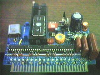
This is the main circuit board for the clock as it appeared during development. I used a zero-insertion-force socket (much bigger than needed, but that's what I happened to have available) for the processor, to avoid the wear and tear of removing and inserting it in the normal socket each time I updated the clock's software. When the clock was finished, I removed the ZIF socket, burned the final software into a one-time-programmable version of the processor (much cheaper than the UV erasable version used for development), and plugged it into the normal socket underneath.
Processor: Microchip PIC16C57, running at 4 MHz. 1083 out of 2048 words (12 bits wide) of program EPROM are used, and 61 out of 72 bytes of RAM.
The four chips in a row are 74141 BCD decoder/drivers, intended for Nixie tube use, each driving one of the Dekatrons. They're not quite appropriate for the job, but they're as close as I'm going to get - there was no historical overlap between Dekatron and integrated circuit technology. The main problem is that they cannot handle enough of a voltage swing to force the Dekatron into a known state, although they work just fine for stepping the tube in either direction. Two complete revolutions will synchronize the tube regardless of its initial state, so this is only a concern at power on, and after a power failure.
|
|
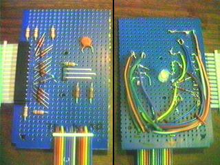
Keypad encoder board, bottom and top. Also includes bi-color LED that indicates valid or invalid keypad entries.
|
|
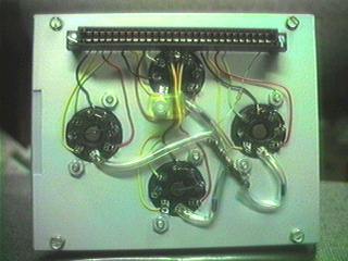
This is the mid-panel of the clock, showing the tube sockets and the edge connector for the main board. There has been some additional wiring done since this picture was taken.
The tube sockets are mounted at an odd angle so that cathode #0 in each tube is at the top.
|
|
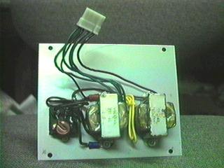
This is the inside of the back panel of the clock. Visible here are the power cord receptacle and fuse holder, a MOV for surge suppression, and the power transformers. The connector plugs into the main circuit board.
|
|
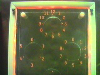
I'm afraid I had to cheat a bit on the front panel - my attempts at hand-engraving the labels looked like crap, so I went to a trophy & engraving shop and had them laser-etch the design (done in Mac CorelDraw 8 LE). 16 tiny LEDs inside the frame illuminate the plastic from all edges: the light is reflected towards the front by the etching on the back side. Unexpectedly, the light is also reflected around the edges, where the panel is glued to the frame. The effect isn't that noticeable in this picture, taken in normal room lighting, but it forms a brilliant rectangle around the clock in the dark. I wouldn't have minded this at all, if only the effect was more evenly visible. Unfortunately, my gluing job was a bit spotty - I used a perfectly clear glue, just so I wouldn't have to worry about such details! I later put a stripe of gray paint all the way around the edge of the panel, which mostly covers this up.
The large circles are cut-outs in a second piece of clear plastic, 3/4" behind the front panel, which hold the tubes in place.
|